MEP Drawings

Types of MEP Drawings

MEP drawings, in the construction industry, is a discipline of civil engineering that focuses on building safety, working, and energy-efficient structures. MEP refers to the mechanical, electrical, and plumbing systems which mainly serve as the backbone to the construction works. The Mechanical part of MEP concentrates on the heating, ventilation, and air-conditioning systems (HVAC system), the Electrical part of this discipline refers to the power supply and the Plumbing part focuses on the water supply and wastewater drainage. Revit MEP, AutoCAD, CADDUCT, Autodesk Inventor, and CAD PIPE are mainly used for preparing these drawings.

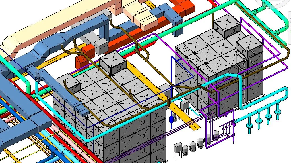
MEP drawing construction serves as a visual means of communicating how its components should be constructed and how they are going to function. They are widely used for sharing ideas across the construction industry. To make coordination drawings more convincing and to minimize perplexity, expert CAD drawing and drafting companies use familiar notation systems and units of measurement. Detailed MEP drawings help in the installation of the ductwork, plumbing, piping, electrical conduits, and fire protection piping such that the routing of each system does not interfere with the other. Every building’s MEP drawing set is unique, and generated after the installation of the building design documents.

Different Types Of MEP Drawing:-

Penetration Drawing

These drawings are designed for penetrants, i.e., for mechanical, electrical, plumbing, and structural items that pass through an opening in a wall or floor, such as electrical conduits, electrical cables, pipes, ducting, and cable trays. Sizing of all openings needs to be done with accuracy as they create a space between the surroundings and penetrants. Therefore, communication between the team members is very important to ensure proper sizing of the openings before these works are carried out. Any changes to these drawings cannot be brought into effect if the penetration works in the building have been finished. Therefore, these drawings need to be well approved with great clearance so that the chances of errors are omitted.

MEP Shop Drawing Detailing

This is done for dimensioning, elevation, and annotations. They are created before the initiation of the construction work of a project. These drawings offer an increased level of detail for fabrication and installation. Some components may require prefabrication including ductwork, air-handling units, and custom piping connections between equipment and building sites. The accuracy of the final dimensions is taken into consideration from shop drawings instead of the design details and layout drawings. Shop drawings are very important for the exemplification of the true image of a construction project. The design needs to be approved by the construction team and after getting the consent, the shop drawings help in determining how the construction process is carried out. Shop drawings can be used to detect any inconsistency before field installation.

Block-out and Sleeve Drawing

These drawings are useful for cement and steel contractors. The drawings are of great help when it is concerned with where to leave space on the floor and ceiling cutouts. Sleeve drawings are used to make sure that the holes left between the floors and the walls are properly placed for piping and ductwork.

Pipe Spool Drawing

A spool is an assembly of pipes and is concerned with the components that can be pre-fabricated in the workshop for installation and shipped to the site afterward for assembling. These drawings act as a guide to the plumbers to figure out what needs to be done. The spools are connected at different junctions throughout any concerned structure. The drawings are optimized to convey all the information that is essential for the fabricators to manufacture and assemble the spool accurately. A spool drawing is obtained after collecting the complete information of all parts welded together into a single drawing.

Coordination Drawing

Coordination is very important for the success of any building project. It simply means avoiding physical conflicts in the layout of the equipment and the routing of ducts, electrical piping, and drainage pipes through the building. When any building project has intense MEP requirements, the risk of interference problems is high. Elimination of coordination problems is a prerequisite for starting the construction work for projects with an intense MEP system. Coordination drawings are necessary to begin the construction work and eliminate any physical conflicts.

As-built Drawing

As-built drawings are made after the construction of the building has been finished. They are used to depict on paper how the building has been constructed. As a matter of fact, as-built drawings are used to make a comparison between what was the planned construction and how the construction has been made in the end. As-built drawings are used to determine the difference between the pre-development and post-development of a building. They are issued to the clients after the project works are wound up. They include everything from the structure to the installation and their details. They are important from the perspective of the client and allow them to survey the product. The as-built drawings play a vital role if there’s any requirement for conducting repair or refurbishment works in the building. After the construction of the building, the as-built drawings can be referred to as shop drawings since they contain in-depth information about the structure of the building. MEP drawings include an accurate representation of designs and assembly instructions. Thus, detailing helps the fabricators, manufacturers, and contractors in getting a clear picture of what is to be supplied and built. These drawings can be used to refer to if there is any fault in the workshop and to detect the exact location to be repaired. In fact, if any component is delivered in damaged condition or goes missing, these original drawing sets can be referred to by the contractors and a substitute can be ordered. This also helps in determining the estimated cost of the components, type of material, and installation techniques beforehand, which minimizes the wastage of time, labor, and overstocking as well. Any precise shop drawings speak for themselves and as a consequence, there is a rapid increase in the brand value.

Contact us for all your MEP BIM Services requirements, we at Monarch Innovation are happy to help.

FAQs

What is MEP in HVAC?

MEP in HVAC refers to the integration of the mechanical, electrical, and plumbing systems required for the proper functioning of HVAC systems in buildings.

What is MEP Specification?

MEP specifications refer to the detailed requirements and guidelines for the mechanical, electrical, and plumbing systems that are part of a construction project. These specifications outline the specific standards, materials, equipment, and installation procedures that are required for the MEP systems to meet the design intent and function properly.

What is the role of MEP in the construction industry?

MEP plays a crucial role in the construction industry as it is responsible for the design, installation, commissioning, and maintenance of the mechanical, electrical, and plumbing systems that are necessary for the safe and efficient operation of buildings.

Construction Documents in construction world

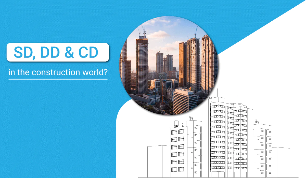
Important Role SD, DD & CD in the construction world

Work must be done in stages to have a comprehensive perspective on design, construction, and project completion. Every stage aims to keep building projects on schedule, within budget, and in compliance with building codes. Stakeholders must be informed and involved throughout the design process for architects to make significant decisions early on in major projects.

Design Development (DD), Construction Documents (CD), and Schematic Design (SD) are terms used in the construction industry, respectively. To increase productivity and cut expenses, AEC companies now prefer to outsource their 3D BIM Modeling requirements to BIM service providers.

Three efficient architectural design procedures are used to separate the design phase. Before beginning the following phase, the client must first approve each phase.

The field of construction combines several distinct areas.

It entails combining many architectural renderings to produce a system that is both practical and aesthetically pleasing.

Research and space planning during pre-design

Habitable structure construction is a labor-intensive procedure that leaves no space for error.

A structure must undergo cycles of modifications and adjustments before construction Document can start, usually using software like CAD.

Schematic Design (SD), Design Development (DD), and Construction Documentation (CD) are CAD drafting processes that guarantee the client’s and architects’ vision and budget result in a plan that can be successfully constructed.

Schematic Design Sets: Establishing the Feel and Look

After conceptual design (CD), a project moves on to schematic design (SD), where the ideas are turned into actual modeling shop drawings.

Before being cleared for construction, these design development sets undergo numerous revisions to account for project needs, customer requests for changes, and licensing authority standards.

Because it doesn’t go into great detail, schematic design is more conceptual. The design will provide a basic exterior, layout of the site, and inner spaces.

Preliminary modeling shop drawings, including floor plans, elevations, and, if necessary, a site plan, are among the deliverables that a design professional will create during this phase. To assist you in obtaining a sense of how the spaces will look and feel, you might also see some sketches or ask your architect to create some computer.

Most of the time, the design won’t contain the final materials, so if you receive sketches or renderings, remember that they don’t always represent the final product.

A story is frequently created by the designer and consulting engineers as part of the schematic design. It gives a general overview of the project and the kind of systems (such as HVAC, electrical, and M&E) the building will employ. Additionally, it aids in the team’s cost-estimating process.

Sets for Design Development – Improving the Design

The designer makes substantial design advancements during this stage. The primary objective of this phase is to identify and develop the project’s crucial components.

More detail has gone into the design of the materials, room sizes, and interior layouts. The engineers will improve the HVAC, plumbing, and electrical systems.

The deliverables include a specification book, which can be regarded as written instructions for the modeling shop drawings, and a series of drawings that are significantly more detailed than those in the schematic phase.

Construction Document Sets – It’s All In the Details

The finished technical data is all that is required. The information necessary to get a construction permit from the relevant local authority will be included in the complete 3D modeling shop drawings and specifications.

Usually, the architect will take care of the permitting for you. Your architect will handle it if the authority has questions, needs more details, or wants alterations to the plans (all of these circumstances are frequent).

The construction documents, also known as the deliverable in this phase, are a comprehensive set of drawings and specifications. These will be provided to contractors to create proposals or quotes for the work and file for the permit. Once more, a revised cost estimate is typically generated as well.

Different phases of the Drafting process-SD, DD, CD

An aesthetically pleasing and well-designed infrastructure is created through the extensive construction process. There can be no room for errors because building a structure is time-consuming and involves iterations of modifications or alterations. Construction drawings are used at various stages to represent the real workflow and developmental stages as the project progress: –

Pre-Design

Site selection, a study of the project’s scope and timeline, an initial cost estimate and some conceptual design concepts are included. Before starting the actual building drawings, every business can obtain a precise understanding of the main parameters related to the pre-design phase.

Schematic Design (SD)

During this phase, architects, the design team, and consultants will develop a theoretical plan that includes design drawings, preliminary license, permit, and permissions research, detailed construction drawings, a detailed description of key building components, schematic site plans, and other critical construction documents.

Design Development (DD)

Detailed information about floating bids and the estimated overall cost of the project is assessed in this phase. Construction drawings and other specifications, such as written documentation containing directions for contractors on any given project, start to take shape after the SD phase. The completion of construction materials, examination of building compliances, and preparation of structural systems are the main causes. After this step, the client can easily approve the necessary comprehensive information regarding floor plans and building sections.

Construction Documents (CD)

The construction documentation process begins after the owners and architects are entirely pleased with the DD and SD plans. The entire design team concentrates on a predetermined set of plans and specifications because it is assumed that no additional editing work is necessary. Construction documents include all relevant information, including structural BIM, MEP, finishing mixes, and material requirements.

Consequently, it is understood that construction documents are a crucial component of building designs. But if you’re seeking a reputable business that can deliver accurate and error-free comprehensive construction drawings, get in touch with C-DESIGN immediately. Here, drawings are created with the aid of technical specialists and architects.

Lastly,

Architectural phases guarantee the timely and efficient completion of construction projects. Architects use these procedures to finish the design within a predetermined time frame.

Outsource your construction project demands to a reputable BIM service provider right away to achieve precise and comprehensive Construction Documents (CD), including Schematic Designs (SD) and Design Development (DD)!

Monarch Innovation creates personalized solutions to assist clients in re-engineering their manufacturing processes and improving organizational effectiveness and results.

Monarch Innovation has a competitive advantage in the sector because of its cutting-edge infrastructure and a staff of highly qualified experts. The two main principles that Monarch Innovation fosters are innovation and creativity.

MEP-BIM-Coordination

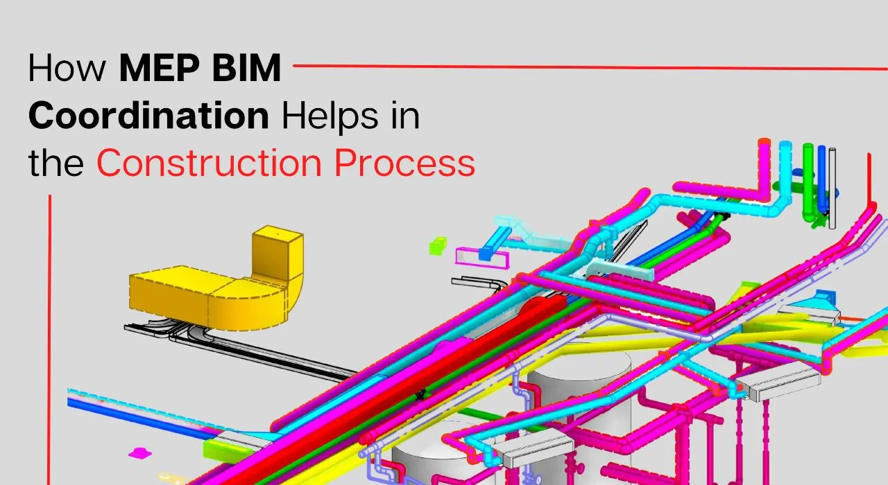
How MEP BIM Coordination Helps in the Construction Process

MEP drawings are a type of civil engineering that concentrates on the safety, functionality, and energy efficiency of structures in the construction business. Mechanical, electrical, and plumbing (MEP) systems are the backbone of building projects. MEP’s Mechanical section focuses on heating, ventilation, and air-conditioning (HVAC) systems, while the Electrical section deals with power supply and the Plumbing section with a water supply and wastewater outflow. These designs are mostly created with Revit MEP, AutoCAD, CADDUCT, Autodesk Inventor, and CAD PIPE.

MEP Coordination in the Construction Process

Before the primary building process begins, MEP Coordination is a strategy for detecting and resolving disputes across various professions such as architectural, plumbing, electrical, mechanical, and structural components. There should be coordination for each discipline, including the changes coming in, to bring these diverse designs into harmony. As a result, MEP BIM Coordination Services is a method for collaborating three primary design verticals, namely architecture, structural, and MEP designs of any infrastructure, and therefore becomes one of the review process’s requirements. Design, construction, and operation and maintenance domain expertise are all required for MEP coordination.

How does BIM help with MEP Coordination?

MEP Coordination functions by synchronizing all the construction work with the other disciplines that make up the structure, fabric, and exterior envelope of the structure. Within the prescribed, structural, and architectural limits, building services coordination allocates vertical and horizontal placements to specific system components. Following that, the coordination experts undertake coordination that focuses on extremely crowded regions to avoid building system interferences. This building service coordination, which takes place throughout the design creation and review process, represents the initial stage in building project coordination. These conflicts or interference must be detected early in the building process since mistakes and redundancy can cost a million dollars if not caught early enough.

Why is it Important to Manage your MEP Coordination Effectively?

We focus on providing clash-free BIM models along with co-ordinated MEP installation drawings, MEP-FS fabrication drawings, MEP-FS construction drawings, MEP-FS co-ordinations, MEP-FS shop drawings, as-built drawings, spool drawings, Architectural design documents, façade drawings, and more, thanks to the healthy expertise of our team in BIM Coordination offerings. We use 3D coordination services to provide an output model that includes Architectural, Structural, and MEP BIM models, as well as clash-free construction drawings sets.

The design inputs are initially coordinated through the BIM model, as a BIM coordination business. Before any difficulties are noticed on-site, any design conflicts or discrepancies in the inputs from various stakeholders are raised. After that, clash-free construction drawing sets are worked on, resulting in a quick time-bound execution. The BIM model is a one-of-a-kind tool for coordinating and detecting clashes between elements from many disciplines. We’ve worked on infrastructure projects and buildings at all levels of development (LOD).

What does an effective MEP coordinator look like?

The MEP sketch structure provides a visual representation of how the components should be built and how they will work. They’re commonly utilized in the building business for exchanging ideas. Expert CAD design and drafting businesses employ known notation methods and units of measurement to make coordinating drawings more believable and to reduce ambiguity. Detailed MEP designs aid in the construction of ducting, plumbing, piping, electrical conduits, and fire protection pipes so that each system’s route does not interfere with one another. The MEP drawing set for each building is unique, and it is created when the building design papers are installed.

The role of a project manager for managing MEP coordination efficiently!

  • Allows you to make the most of your building’s area.
  • Brings together the builder, contractor, architects, and engineers to address concerns early on and create a precise and correct design for the building project.
  • When we analyze the model with conflict detection software such as Navisworks and Revit, we can limit the number of change orders during on-site construction work, which can lead to human errors, saving money, time, and manpower for the building owner, contractor, and firm involved.
  • It allows numerous engineers to collaborate on a single model, which is then synchronized to reflect the changes made by each user in the project.
  • Based on the conflict detection reports, which include thorough mapping of the portions of the present structure, the engineers may make design alterations and enhancements to the existing structures, and this amended design can then be passed on to the contractor.

BIM-based design and construction (part of Virtual Design Construction) enable data-driven cooperation between architects, structural engineers, and MEP engineers from the start, increasing design confidence and simplifying phasing. As a result, the design-to-construction process has been drastically altered.

BIM Benefits

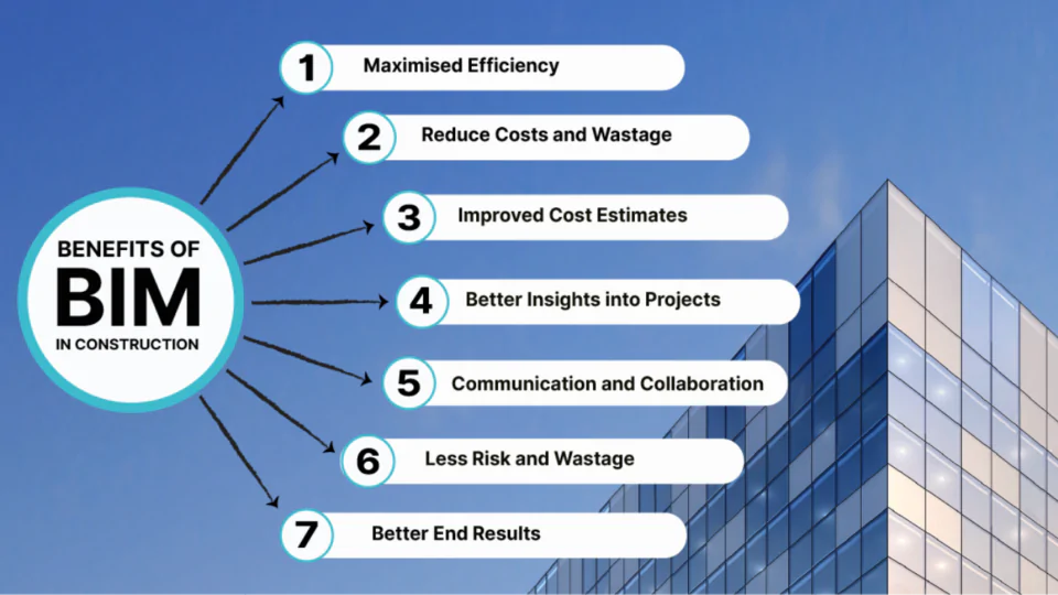
Benefits of Building Information Modeling (BIM)

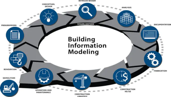
BIM, an acronym for Building Information Modeling, is more than a technology, being a complex design and construction process, which helps in the creation of modern and innovative infrastructures. It is basically a digital and visual representation of information of a facility. It is the process of the creation and management of information in construction projects.

The 3D building model is one of the outputs of the BIM modeling which digitally represents all the aspects concerned before the actual construction of the building. Besides being a special construction software, BIM is an overall approach to design and plan a construction project.

BIM technology is used to make detailed 3D models of buildings. In the modeling stage, the architects experiment with the design and detect any issues before implementing their ideas to initiate the construction work. The information and ideas regarding the project are stored in a shared location where it becomes easily accessible for the architects, clients, and constructors. They usually use cloud-based software, which can be accessed from anywhere by anyone with secured permissions by connecting to the server. The constructors and architects construct the building with an established workflow in their minds. In addition to that, it becomes easier for them to visit the BIM model and workflow during the process and make the required adjustments whenever needed. After the completion of the structure, architects can hand the BIM model to the clients because the models can help in locating the HVAC systems or renovating the structure in the future.

Importance of BIM

  • BIM database improves collaboration among the teams involved and provides a store of architectural and design data which can greatly be used for 3D modeling and software simulations. These can be used for designing and structuring and gives room for the creative deployment of new materials and design concepts.
  • 3D models can be used for design purposes and it makes the sharing of ideas with clients simpler. With 3D modeling, it becomes easier for individuals to view plans and visualize the final results without any prior or special architectural training. Nowadays, it has become easy to get a 3D model of any structure with the help of BIM before the construction work is initiated, as BIM creates them as an automatic part of the designing process.
  • BIM allows the architects, structural engineers, and builders to analyze information in the format required, without any duplication of the data. The design such as schedules, color-filled diagrams, drawings, and 3D models can be approached through databases without implementing any manual techniques.

Benefits of Building Information Modeling

  • Enhanced communication and teamwork

    BIM framework ensures better teamwork, management, and sectioning sets of drawings that are usually impossible to understand through paper drawings. BIM allows uninterrupted interfacing with all the project areas. BIM framework such as the BIM 360 framework facilitates better project work distribution among the members involved and project planning management that makes it quite easier for the project stakeholders to understand.
  • Cost assessment

    BIM provides the construction cost estimates way before the beginning of the construction phase. Tools like BIM 360 Docs can be used to estimate costs that are related to materials and their shipping, shipping of prefabricated or modular pieces, and labor. BIM modeling can help in choosing more cost-effective materials, streamline the workflow of the construction, buy the materials at their lowest market price and reduce human errors which lead to delays in the project.
  • Monitoring changes

    Construction project undergoes several modifications before the construction is carried out on the field. BIM makes it easier to monitor these modifications to return to an earlier design of the model if the new one is erroneous. This feature helps the project designers save their precious time as compared to the 2D drawings since there is no requirement of redrawing the designs again.
  • Visualization of the project

    BIM offers tools that help in proper planning and clear visualization before the initiation of the construction work. 3D visualization and the simulation of the surface area help the client to get the post-construction visualization of the infrastructure thus facilitating easy modifications prior to the construction stage.
  • Effective coordination

    BIM provides easy and effective coordination among the various teams involved. It detects all the internal and external clashes and conflicts between any field. Software like Autodesk BIM 360 glue can be employed to prevent clashes through automated clash detection. Clash detection limits the number of repairs or reconstruction required.
  • Lowered risks and expenses

    BIM helps a lot in lowering expenses. Good coordination with the contractors can reduce the cost of insurance, lower the number of generic versions and reduce the risk of claims. Reviewing the project at its preconstruction stage can reduce the number of unused material wastes. Most of the firms employ construction technology and BIM to reduce the overall risks and expenses.
  • Sequence and schedule

    BIM technology help saves a lot of time by reducing the lifespan of the project cycle and avoiding any delays in the scheduling of the construction. It enables precise planning and improves collaboration which increases the chance of the completion of the project within the stipulated time.

Undoubtedly BIM is advantageous to both the construction industry and the business market. So, you can definitely prefer Monarch Innovation for the BIM modeling. Monarch Innovation provides you with the facility of automatic model checks and uses BIM data as a source of information. Monarch Innovation provides you with the tools that are needed to access, validate and use building information that helps you to meet your expectations with ease.

5D BIM Plan

5D BIM: How it will Help the Construction Industry

5D BIM (Building Information Modelling) is a highly effective system that helps plan and execute real construction through a digital look of a physical structure. It is an intelligent model-based process that connects AEC professionals so that they can design, build and operate buildings and infrastructure more efficiently. It goes further than just the building’s physical appearance and includes information about every component that goes into a project. This helps the designers, whether an architect, an engineer or a construction drawings professional, to create and design more efficiently as compared to other tools in the market today.

BIM is a process of creating information models formed of graphical and non-graphical information in a shared digital space known as a common data environment (CDE).  The BIM process helps in planning the project stages, components, and construction expenses.  When an information model is created, scheduling data can be added to different components generating accurate program data for the project, this is 4D BIM. The next step involves producing accurate cost estimates from the components of the information model, this process is termed 5D BIM.

BIM OBJECTS:- There are primarily two types of BIM objects –

  • Component: The component objects are mainly the building products that have fixed geometrical shapes such as windows, doors, boilers, etc.
  • Layered: The layered objects are the building products having no fixed shape or size such as roofing, walls, and ceilings.

BIM objects may be categorized under –

  • Generic: These objects, often referred to as library objects, are used during the beginning phase of designing as a visual expression for a specific object to be selected at a later stage.
  • Specific: These objects, often termed manufacturer objects, are used to represent a manufacturer’s specific products.

BIM objects are available in a range of file formats that are suitable for use in software like Bentley ACEOsim, Graphisoft ArchiCAD, Revit Architecture, and Nemetschek Vectorworks.

There are certain places where one can expect the availability of BIM objects. NBS National BIM Library is one of the library sites where one can find BIM objects. It serves as an online environment that is created to store BIM model files. In the case of the NBS National BIM Library, all BIM objects are authorized to NBS standards. It ensures the user is able to select and use BIM objects that are compatible across all the working platforms.

5D BIM modeling, 5-dimensional Building Information Modeling, is the extraction or development of a valued parametric building model within a virtual model. It visualizes a project that consists of budgetary and cost considerations associated with the project.  It is a five-dimensional plan showing the physical and functional aspects of any project. 5D BIM technology allows the involvement of more people in the conversation from the onset instead of working in isolation waiting to provide information about their piece of the project when it is time. It automatically generates accurate data and estimates costs for construction projects. 5D is productive in all aspects of the construction industry but the ones who are most benefited from this extra dimension are the project managers.

5D technology involves the extraction of quantities from the BIM model and aims to help the site team to manage the material resources based on the master project schedule. The extracted quantities are later used to generate a material management sheet. The sheet aids in extracting exact quantities of the materials based on the master project schedule. The team can extract the material quantity from any given time frame in the project cycle. It really helps in the reduction of the project waste since there will be no material dumping required on-site and an exact quantity of material can be ordered.

5D Macro BIM is the artistic form of design with the strategic function of a building’s architecture, and also increases transparency in the process. With 5D Macro BIM, one can easily model, design, and implement creative design concepts, clever exterior finishes, innovation layouts, uniquely shaped and aligned departments and floors in varying sizes. 5D Macro BIM modeling allows every element from square footage to pricing, timing, layouts, and more to be conceptualized. Using a BIM in the 5D approach allows a strong vision to crystalize early in the process so that a building’s element and detail align with big picture goals. Under the proper guidance of a full project team and estimation experts, owners can come up with informed decisions and be confident of getting the right facilities. It allows for greater participation in the design process. It has been very helpful in healthcare construction settings because it delivers more nuanced insights to owners to balance a facility function, cost, and ease of use for patients and visitors. For Example, A hospital in Texas wanted three different departments to be located on the ground floor.  Designers easily clicked and dragged color-coded sections of the designs to denote each department, shrinking or enlarging them based on the suggestions. These changes produced real-time shifts in the projected cost. For example, Korte designers helped the owner of a new healthcare facility in North Carolina to decide how to maximize finite resources by isolating individual floors in the design to examine the varying costs. This proved to be helpful in minimizing expenses in some places to allow more investment in others.

BIM software can affect the construction management process powerfully when it comes to cost-related information. With its aid, data connected to cost care are updated continuously with the progress of the project, i.e, the cost is dynamically evolved and readjusted rather than being solely defined at the beginning of the project. This makes it easier for the project managers to keep a track of the changes while keeping the project running within the agreed budget. It may be successful in improving cost prediction and resource management.

BENEFITS OF BIM

  • It improves onsite collaboration and communication. BIM association with several designing tools like Autodesk’s BIM 360 enables it to be smoother across different areas in the project. With cloud-based tools such as Autodesk’s BIM 360, Its ecosystem allows the team to share project models and coordinate planning, ensuring all design stakeholders have insight into the project. With cloud access, there’s no inconvenience to take the office to the field. With apps such as Autodesk’s BIM 360 tools, drawings and models can be viewed onsite on their devices, ensuring they have access to up-to-date project information at any time.
  • Model-based cost information – Including estimators earlier in the planning stage allows for more effective construction cost estimation that leads to the growth of model-based cost estimating. Using BIM tools such as Autodesk’s Revit reduces time consumption and allows estimators to focus on higher-value factors like identifying construction assemblies and factoring risks.
  • Visualization of projects in preconstruction – By using BIM, one can plan and visualize the entire project before the construction work is initiated. Space use simulations and 3D visualizations give an idea of how space will look like and also offers the ability to make changes before the construction work is initiated.
  • It increases productivity and prefabrication. It can be used to generate production drawings and databases for manufacturing purposes, allowing for prefabrication and modular technology uses. By designing, detailing, and building offsite in a controlled environment, one can diminish waste, increase efficiency, and reduce labor and material costs.
  • It can improve construction safety by highlighting the dangers before they act as problems and avoid physical risk by visualizing and planning site logistics beforehand.
  • It helps in the reduction of the amount of rework needed on a given job by avoiding clashes. One gets the opportunity of planning things in a proper manner to avoid last-minute changes.

BENEFITS OF 5D BIM

5D BIM
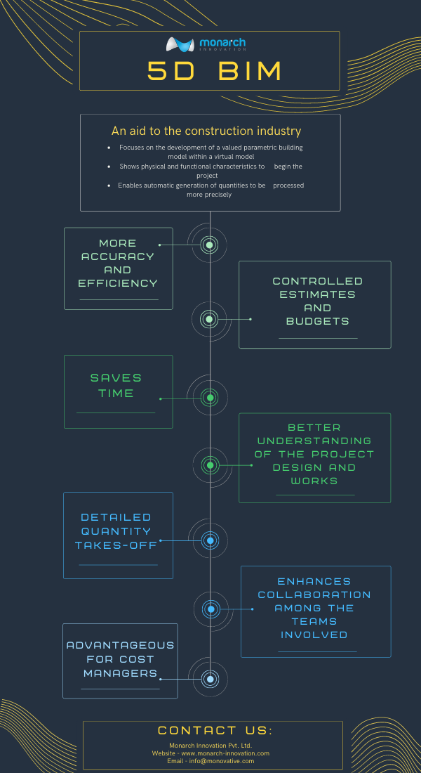
  • More accuracy and efficiency- decreases manual efforts with evaluating assets and computing costs while additionally reducing errors.
  • Gain complete control over project cost estimates and budget.
  • With 5D BIM, it becomes easier to recognize, evaluate and record any changes made in the models.
  • Saves time- provides shorter execution life cycles and saves time from documentation to material costs with accurate data unnecessary wastage and clashes are eliminated leading to shorter project execution life cycle.
  • A better understanding of the project design and cost drivers. The project team will have a concise and accurate description of scope costs and budgets.
  • Frees cost managers from tedious and time-consuming manual qualification.
  • Will also allow engineers and architects to experiment with innovative workplace design.
  • 5D BIM makes maintenance operations easier and increases gross productivity.
  • Helps in predicting the rough life of the building and analyzing which materials in the building could be used after demolition.
  • It enhances collaboration between teams involved in construction.
  • Detailed quantity takeoffs- as estimators spend most of their time in creating quantity takeoffs, 5D implementation paves the way for automation of the development of quantity take-offs. This helps in saving time which can be used by estimators in several areas like generating pricing models or accessing financial risks.
  • BIM allows all the stakeholders to work on a single model from various locations and devices. All skateboarders can work simultaneously and make changes together to augment the collaboration process.

BENEFITS OF 5D MACRO BIM

  • BIM allows all the stakeholders to work on a single model from various locations and devices. All skateboarders can work simultaneously and make changes together to augment the collaboration process.
  • Macro BIM features allow individual investors and real estate developers to evaluate the practicality and costs of building the project on a construction site.
  • Macro BIM focuses on construction site requirements and large-scale building massing. The value of macro bim models accrues over time and across projects using the large data sets that are increasingly available.

WHAT DOES BIM MEAN FOR THE COST MANAGERS?

5D BIM is a strong tool for cost managers. It adds much more flexibility to work and improves their

decision making process. 5D cost managers have the benefit of re-estimating the developing design for

infinite times and can give feedback accordingly on the estimated variances and corrective suggestions.

Cost managers can very quickly determine the quantity of a particular component, applying rates to several quantities to provide an overall estimate for the package.

Cost managers can forecast estimations and update design teams with feedback for various project stages. As cost managers have an in-depth view of what items needed to go onsite, material logistics can be planned accordingly. 5D cost estimation helps cost managers to get precise construction costs and estimates. It also provides shorter project cycles and saves construction time.

SCOPE

Data connected to costs are continuously updated as the project progresses. This 5D BIM makes.

project managers to monitor changes while keeping the project running within the agreed budget. This can improve cost predictability and resource management. Applications supporting BIM in android and ios will help contractors designers and the AEC industry, in general, to constantly keep a check on the developing designs of the model and apply corrections immediately creating a better commutation with the skateboarders of the project involved. The cost estimation will allow clients to visualize the impact of changes in the design and timeline on project costs. This will help reduce delivery time, enhance quality control, eliminate budget overruns and add significant value to a project.

Monarch Innovation has been fulfilled the needs of the construction industry with customized and standard solutions irrespective of size and project status whether residential, industrial retail, healthcare, or education. Contact Us for more information.

BIM and CAD

What is the Difference Between BIM and CAD Files?

To understand the difference between BIM and CAD files you must know the concepts of BIM and CAD files and what are their uses.

CAD stands for Computer-aided design whereas BIM stands for Building Information modeling. Computer-aided design programs are used by engineers to assist with the creation, modification, analysis, or optimization of designs with the use of computer systems such as TinkerCAD, Autodesk’s AutoCAD, etc.

BIM is an acronym for Building Information Modeling. BIM is a new-age process used by architects, engineers, and construction professionals to design and construct buildings and infrastructure more efficiently.

CAD and BIM files have different uses and differ in many ways. You cannot replace one with another. To know the difference let’s understand the concepts in details.

 What is CAD and who uses CAD?

CAD is a highly decorative program that is used in the creation of making 2D drawings and 3D models using computer systems. The 3D AutoCAD CS software has been used by these engineers for decades helping them to design and manufacture complex products efficiently and effectively saving a lot of time.

CAD was developed back in 1963 by Ivan Sutherland that broke new ground records in 2D and 3D modeling and visual simulation. Engineers could directly draw on a CRT with the use of a light pen.

CAD programs are widely used by engineers in civil engineering and plant design in various industrial and manufacturing companies. These widely used computer software programs can help you explore and design ideas through photorealistic renderings and simulate how a design performs in the real world

Advantages of CAD

  • Easy to use, edit designs and modify drawings using computer-aided software
  • CAD models offers improved accuracy over manual drawings.
  • When a certain part or aspect of the drawing is required, duplication of labour is removed as everything is available and reproducible digitally
  • CAD software has a paper trail to refer back to automatically for any digital design you make

Disadvantages of CAD

  • May cause complacency as designers slip into the same design from their library each time and cause your designs to look the same
  • CAD allows different aspects of design to be put together but leaves out the bigger picture and the real-world issues of the design when doing so

What is BIM and who uses BIM?

BIM is an advanced 3D model-based program mainly used by architects, engineers, and contractors to design and build commercial buildings and infrastructure. With the help of BIM files, you can analyze and evaluate design decisions before starting the project.

BIM works as a single communication channel between work process and technology to work on the project collaboratively and efficiently. BIM is a digital 3D model based representation and shared resource that can be used by multiple parties involved in the design and build the structure from the beginning till the end.

This 3D model-based representation makes itself a cost-efficient and time-saving process and the chances of making errors are minimal and if any, that can be discovered at an early stage. BIM model provides data that can span the operation and management aspect of the construction project, and this information is later available to the structure owners as well.

Nowadays BIM is being commonly used by manufacturing engineers and contractors to provide a piece of detailed product information in different BIM formats. BIM software tools (the most common one being Revit) have redefined the design and construction workforce amongst the architectural and engineering design firms as well as contractors.

To know more about BIM modeling and using BIM solutions to make your construction project efficiently smoother, reach out to us at Monarch Innovation.

Advantages of BIM

  • Teamwork is enhanced as communication across all construction phases and techniques is coordinated
  • Any change made to the design either individually or simultaneously by different team members is dynamically shown and monitored
  • Even at the planning stage, the final structure or its components can be visualised
  • Any clashes between different sets of data in regards to components or between contractors can be identified and sorted before any cost is incurred in reversing the change.

Disadvantages of BIM

  • BIM software requires initial software investment and powerful PCs for processing
  • Staff and engineers need to be trained in BIM to make full utilisation of its features across projects
  • Although it might now sound like a big deal trust and change in work culture is a big issue for various teams working collaboratively on the project to make the most of their data. All parties need to be willing to share the data and invest in understanding its importance
  • The client often has no idea of the superior features of BIM modelling and don’t utilise the information presented by BIM to the full extent, wasting the time and effort of the construction team

CAD usage and How Does It Compare To BIM?

CAD models have been useful for a long time to help the architect to understand and render the modifications, development and optimization of the entire construction process. CAD has replaced manual drafting and helped the engineers, architects, and construction managers in creating designs in either 2D or 3D models so that they can visualize the construction of the project.

With the help of CAD now it is easier to make more accurate representations and modify them to improve design quality. It also helps the subcontractors to add up more details to the model.

Nowadays you can create a backup of your drawings and plans in the cloud storage which can be easily accessible by the contractors to CAD-based drawings/plans at the worksite making plan out the modifications easily. It also helps to identify the possible impact the changes might have on construction and adapt as needed and improves communication. This ultimately increases productivity and the effective utilisation of information.

Designers can now create more comprehensive designs considering other elements like electricity, plumbing, structure etc. which has only been possible with the help of CAD. This ultimately enables fewer work changes and a reduction in errors. The technological impact of CAD has been a game-changer in the industrial markets transforming construction into a technology job.

Many Engineers and contractors have been anticipating that these new-aged BIM software tools will become the focus of every new commercial building projects due to its collaborative process that allows architects, engineers and other constructional professionals to construct or design within a single 3D model.

One of the largest upgrades on BIM software from previous CAD software is that BIM allows work in 5 dimensions – time, cost, length, breadth and width. CAD allows work in only length, breadth and width. One can easily understand how this is a game-changer in the construction industry across project teams.

Today’s architects and engineers rely on BIM software to build and design 3D models of their buildings and infrastructure. The power of visualizing something in 3D gives the design and construction team a pretty accurate estimate of what the final structure should look like as well as the cost estimations along the way.

BIM Vs CAD – Which to Use?

CAD is mainly used for industrial design of mechanical and electrical work such as aeroplanes, mobile phones etc. On the other hand, BIM is used in the design and manufacturing of buildings and infrastructure such as airports, schools, hospitals, etc., and has become the most preferred software in the industrial markets. These files also give you the feature to detect virtual collision and construction-related errors before starting the actual work.

BIM models are designed for flexibility i.e., you can zoom in and zoom out and make a detailed design of your building. CAD is more likely a static, high-detailed component that has only one visual representation. A changeable BIM model will enable the CAD file to be viewable in its original form with full detail up to a definite zoom level.

Converting CAD files to BIM file types can result in blurring of CAD components while adjusting the scale of the model whereas adjusting the scale further can cause the image to discolor, appear as a black splotch, or fade from the screen. Hence CAD files fail to self-correct these adjustments when they are incorporated into BIM files.

CAD to BIM conversion – what are the advantages?

Although CAD has ruled the roost for a long time, it is now time to hand over the throne to Revit BIM models, which offer a far larger set of advantages. A lot of CAD designs are being converted to BIM models for high-rise or large scale construction projects because:

  • BIM models are more detailed, provide more options for analysis and deconstruction of the data.
  • BIM allows work in 5 dimensions – time, cost, length, breadth, and width. CAD allows work in only length, breadth, and width.
  • BIM models are easier to manipulate and use to incorporate new changes and design integrations.
  • Revit is a software that is now widely used, making it easier to communicate between stakeholders and project teams.
  • BIM models help in scheduling the timeline of the construction stages, estimating the cost, and billing the quantities of each component
  • BIM modeling can cover the whole lifecycle of the project – right from the design conceptualization to construction to demolition.
  • As all the information is pooled at a common spot and changes can be made dynamically, it dramatically reduces the loss of information across the pipeline, and increases efficiency.

To make your project lifecycle come alive with BIM solutions, reach out to Monarch Innovation and let our professional team of consultants and construction experts handle your challenge.

For more information, contact at info@monovative.com Or Call on +91 9974852647

Previous Next
Close
Test Caption
Test Description goes like this
Add to cart
Open chat
Hello,
Welcome to Monarch Innovation!

How Can I Help You..?