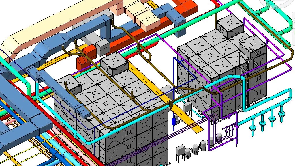
MEP drawings, in the construction industry, is a discipline of civil engineering that focuses on building safety, working, and energy-efficient structures. MEP refers to the mechanical, electrical, and plumbing systems which mainly serve as the backbone to the construction works. The Mechanical part of MEP concentrates on the heating, ventilation, and air-conditioning systems (HVAC system), the Electrical part of this discipline refers to the power supply and the Plumbing part focuses on the water supply and wastewater drainage. Revit MEP, AutoCAD, CADDUCT, Autodesk Inventor, and CAD PIPE are mainly used for preparing these drawings.
MEP drawing construction serves as a visual means of communicating how its components should be constructed and how they are going to function. They are widely used for sharing ideas across the construction industry. To make coordination drawings more convincing and to minimize perplexity, expert CAD drawing and drafting companies use familiar notation systems and units of measurement. Detailed MEP drawings help in the installation of the ductwork, plumbing, piping, electrical conduits, and fire protection piping such that the routing of each system does not interfere with the other. Every building’s MEP drawing set is unique, and generated after the installation of the building design documents.
Different Types Of MEP Drawing:-
Penetration Drawing
These drawings are designed for penetrants, i.e., for mechanical, electrical, plumbing, and structural items that pass through an opening in a wall or floor, such as electrical conduits, electrical cables, pipes, ducting, and cable trays. Sizing of all openings needs to be done with accuracy as they create a space between the surroundings and penetrants. Therefore, communication between the team members is very important to ensure proper sizing of the openings before these works are carried out. Any changes to these drawings cannot be brought into effect if the penetration works in the building have been finished. Therefore, these drawings need to be well approved with great clearance so that the chances of errors are omitted.
MEP Shop Drawing Detailing
This is done for dimensioning, elevation, and annotations. They are created before the initiation of the construction work of a project. These drawings offer an increased level of detail for fabrication and installation. Some components may require prefabrication including ductwork, air-handling units, and custom piping connections between equipment and building sites. The accuracy of the final dimensions is taken into consideration from shop drawings instead of the design details and layout drawings. Shop drawings are very important for the exemplification of the true image of a construction project. The design needs to be approved by the construction team and after getting the consent, the shop drawings help in determining how the construction process is carried out. Shop drawings can be used to detect any inconsistency before field installation.
Block-out and Sleeve Drawing
These drawings are useful for cement and steel contractors. The drawings are of great help when it is concerned with where to leave space on the floor and ceiling cutouts. Sleeve drawings are used to make sure that the holes left between the floors and the walls are properly placed for piping and ductwork.
Pipe Spool Drawing
A spool is an assembly of pipes and is concerned with the components that can be pre-fabricated in the workshop for installation and shipped to the site afterward for assembling. These drawings act as a guide to the plumbers to figure out what needs to be done. The spools are connected at different junctions throughout any concerned structure. The drawings are optimized to convey all the information that is essential for the fabricators to manufacture and assemble the spool accurately. A spool drawing is obtained after collecting the complete information of all parts welded together into a single drawing.
Coordination Drawing
Coordination is very important for the success of any building project. It simply means avoiding physical conflicts in the layout of the equipment and the routing of ducts, electrical piping, and drainage pipes through the building. When any building project has intense MEP requirements, the risk of interference problems is high. Elimination of coordination problems is a prerequisite for starting the construction work for projects with an intense MEP system. Coordination drawings are necessary to begin the construction work and eliminate any physical conflicts.
As-built Drawing
As-built drawings are made after the construction of the building has been finished. They are used to depict on paper how the building has been constructed. As a matter of fact, as-built drawings are used to make a comparison between what was the planned construction and how the construction has been made in the end. As-built drawings are used to determine the difference between the pre-development and post-development of a building. They are issued to the clients after the project works are wound up. They include everything from the structure to the installation and their details. They are important from the perspective of the client and allow them to survey the product. The as-built drawings play a vital role if there’s any requirement for conducting repair or refurbishment works in the building. After the construction of the building, the as-built drawings can be referred to as shop drawings since they contain in-depth information about the structure of the building. MEP drawings include an accurate representation of designs and assembly instructions. Thus, detailing helps the fabricators, manufacturers, and contractors in getting a clear picture of what is to be supplied and built. These drawings can be used to refer to if there is any fault in the workshop and to detect the exact location to be repaired. In fact, if any component is delivered in damaged condition or goes missing, these original drawing sets can be referred to by the contractors and a substitute can be ordered. This also helps in determining the estimated cost of the components, type of material, and installation techniques beforehand, which minimizes the wastage of time, labor, and overstocking as well. Any precise shop drawings speak for themselves and as a consequence, there is a rapid increase in the brand value.
Contact us for all your MEP BIM Services requirements, we at Getra Innovation are happy to help.
FAQs
What is MEP in HVAC?
MEP in HVAC refers to the integration of the mechanical, electrical, and plumbing systems required for the proper functioning of HVAC systems in buildings.
What is MEP Specification?
MEP specifications refer to the detailed requirements and guidelines for the mechanical, electrical, and plumbing systems that are part of a construction project. These specifications outline the specific standards, materials, equipment, and installation procedures that are required for the MEP systems to meet the design intent and function properly.
What is the role of MEP in the construction industry?
MEP plays a crucial role in the construction industry as it is responsible for the design, installation, commissioning, and maintenance of the mechanical, electrical, and plumbing systems that are necessary for the safe and efficient operation of buildings.


